DUAL-RELAY
OPTION
INSTALLING THE DUAL-RELAY OPTION BOARD
To
install the dual-relay option board, follow these steps (refer to the
Figure 10-1):
 Caution:
the meter has no power-on switch, so it will be in operation as soon as
you apply power. Caution:
the meter has no power-on switch, so it will be in operation as soon as
you apply power.
 Important:
Disconnect the power from the unit before installing this option board. Important:
Disconnect the power from the unit before installing this option board.
1. Hold the board in a horizontal position, with the TB3 connector
facing towards the rear of the meter.
2. Line up the 3 connectors located on the back side of the board
with pin groups J3, J4 and J5 on the mother card.
3. Push connectors down to secure on relay board.
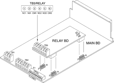
Figure 10-1 Dual-Relay Connections
SETTING
UP THE DUAL-RELAY BOARD
You may enter a setpoint from -99999 to 999999 with a decimal point in
any of the following positions: 9.9.9.9.9.9. After applying the scale
factor and offset, the displayed measurement is compared to the setpoint
values.
LO ALARM
Displayed value is less than Setpoint
LO HI ALARM
Displayed value is more than Setpoint
HI HYSTERESIS
Relay 2 is energized when display value is more than Setpoint HI.
Relay 2 is not energized when display value is less than Setpoint LO
Setpoint Example: Setpoint HI is 500.0 and Setpoint LO is 100.0.
Reading changes from 0 to 600 and back to 0. Figure 10-2 illustrates Table
10-1.
Setpoint
Example (Table 10-1)
|
Alarm
Status
|
|
Reading
|
LO(Relay
1)
|
HI(Relay
2)
|
HYS
|
|
0
|
On
|
Off
|
Off
|
|
99.9
|
Off
|
Off
|
Off
|
|
300
|
Off
|
Off
|
Off
|
|
500.0
|
Off
|
Off
|
Off
|
|
500.1
|
Off
|
On
|
On
|
|
600
|
Off
|
On
|
On
|
|
500.1
|
Off
|
Off
|
On
|
|
100-500
|
Off
|
Off
|
On
|
|
99.9
|
On
|
Off
|
Off
|
|
0
|
On
|
Off
|
Off
|
STANDARD
RELAY OPTION
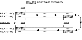
RELAY
OPTION WITH HYSTERESIS
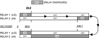
Figure 10-2. Setpoint Example Illustration
To convert Setpoint LO to a second high setpoint, set software switch
3 of the configuration menu to 1 (CONFIG = XX1XXX). LO ALARM becomes
active when the reading is greater (more positive) than that setpoint.
To convert both setpoints to latched setpoints, set software switch 2
of the configuration menu to 1 (CONFIG - X1XXXX). When relays are energized,
they stay energized until a Reset (either front-panel or back connector
reset).
ELECTRICAL
CONNECTION AND SPECIFICATION
Each relay has a form
C contact. Relays are rated at 28 Vdc or 250 Vac at 5A. Refer to Figure
10-1 and Figure 10-3 to locate contacts and S5 switch.
* TB3-1 is
a normally closed contact of relay 1.
* TB3-2 is a normally open contact of relay 1.
* TB3-3 is a common contact of relay 1.
* TB3-4 is a normally closed contact of relay 2.
* TB3-5 is a normally open contact of relay 2.
* TB3-6 is a common contact of relay 2.
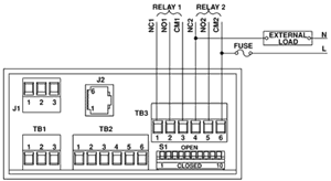
Figure 10-3.
Electrical Wiring for Relay Connections
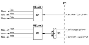
Figure 10-4. Dual-Relay Connections
|